Triumph 675 Forums banner

Daytona to StreetFighter Conversion - Project Trixie Transformation

186K views 331 replies 77 participants last post by  Ruby Racing  
#1 ·
Having been inspired by the likes of 1 riktig svensk I am about to undergo my very own Daytona to Street Triple conversion. I plan to keep you informed about my progress, with plenty of pictures.

So first off, why am I doing this? Why am I going to rip apart a beautiful looking bike? Why don’t I just buy a Street Triple? Well, I love the Daytona, the engine the handling, etc. I just can’t get on with a sports bike on the road. I find them too uncomfortable. I have a GSX-R1000 that I race anyway, so I don’t need another sports bike.

Why not buy a Street Triple I hear you cry? Well, no offence to those who own one, but I don’t like the looks. The twin cans and twin headlights don’t do it for me. I love the Daytona’s rear end though.

As we often read in the bike mags, when a manufacturer turns a sports bike into a road bike (like R1 to Fazer), they detune the engines, fit cheaper suspension, brakes, etc and basically take away all the good bits.

So that is pretty much it. Plus I wanted a project bike. So that’s what I have, a 2006 Daytona. Not even a crashed one. I did consider that, but where I live it’s hard to get hold of crash damaged bikes as they are all shipped off to the UK.

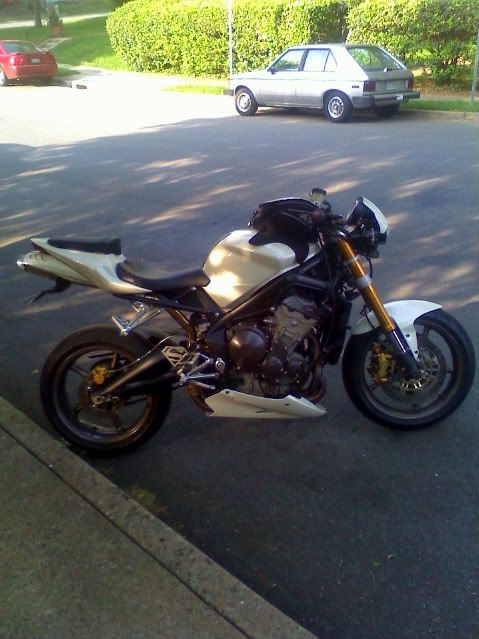
Here is a pic of the starting point. Why Trixie Transformation? I name all my bikes, but my wife beat me to it and named her Trixie.
 

Attachments

#81 ·
Great thread this, loving the day by day updates.

As for the project itself - how could you do that to such a great looking bike?? I so can't wait to see the end result!!

Fair play to you anyway, it's a ballsy shout and I hope you get the result your hoping for.

Good luck :cool2:
Cheers dude. Check out my very first post for the answer to your question (in blue).
 
#82 ·
Day 15

Day 15

Stepped away from the wiring today. I need to get my new bikini fairing attached so that I can sort out the routing of the wiring for that. It wont fit straight on, so some metal brackets are going to be made to adapt it. I'm doing a TIG welding course at the moment so I hope to make them myself. I'm only 4 weeks into the course, so I may be getting a bit ahead of myself there.

I also need to make an adapter plate for the speedo as the plastic pins on the rear of it don't line up with those on the bikini fairing mount. As if I would be that lucky! So I started making a mock up of that in wood to see if it would work and more importantly to make a pattern for the real thing, which will probably be made of aluminium.

Not a quick job, but like everything if you want to get it right then take your time. I need to utilise the speedo mounting holes on the bikini fairing mount to attach the bracket to and then after that work out where the holes for the Daytona speedo can go. Luckily the holes for each are in different place, otherwise it would have been much more difficult. Here are some pics of the mock up. Note the copious use of a Corn Flake packet. Blue Peter was a great teacher! That's all, because like all "quick" jobs, it actually took a lot longer than first anticipated.

I have started with 20mm blocks on the rear of the new mount bracket as I need to have space for the plastic pins to push through. At the moment it looks like I can get away with shorter length blocks, but I also need to have room for the loom connection on the rear of the speedo and I wont know how much space that requires until I fit it. I'm hoping to reduce the size as much as possible and this test will let me know how deep theses mounting blocks need to be.
 

Attachments

#83 · (Edited)
Day 16

Day 16

Continued work on the brackets. A lot of trimming, adjusting, fitting then taking it off, etc, to try and get a final design. For the speedo bracket I started off with 20mm blocks on the rear, but this sits the speedo quite high. Not a problem in itself, it just looks a bit biff. This height was determined by the need to be able to route the speedo loom connection on the underside. Then I looked at the fairing mount for a bit and have decided I can route the cable through the fairing mount by cutting some holes, then I can have it exit the fairing mount right behind where it needs to connect to the speedo. By cutting these holes it means the 20mm blocks can now be reduced to about 3mm, which will make things a lot tidier. The pictures show it with the 20mm blocks on the rear side and from the photo from the front you can see the gap where the loom cable attaches to the rear of the speedo.

I also continued work on the brackets to attach the faring mount to the frame. I'm utilising the existing mount holes that are in the headstock which would normally be use to mount the intake tube. It's not a straight forward match (as if!?) as the spacing between the lower two holes compared to the top two holes differs in width by about 3mm. Also where my brackets attach to the fairing mount means that they are too wide to fit in the intake hole in the frame. So I need to shim them inwards on the fairing mount so they fit snug into lower locating holes in the frame and then shim the top of the brackets outwards to meet the inside of the intake hole in the frame. This will just be a case of welding some plates onto the the metal bracket that I make. I hoped to work out how much shimming was needed with my wooden mock up, but they bend too easily because they are wood. So I will make the brackets in metal and then will be able to calculate correctly the size of shim I will need as the metal will not bend as I'm using about 3mm steel. Next step is to make the metal brackets, so watch this space.
 

Attachments

#84 ·
Sorry there have been no updates recently. I'm on holiday in Florida (by the way it's been flippin' cold! And I'm fed up of listening to Screamin' Eagle pipes) and not far away from a little place called Daytona. How apt. Should have an update in a weeks time when hopefully I will have made my metal brackets. Watch this space.
 
#85 ·
Day 17

Day 17

Finally got back to work on my project. I had my welding class on Thursday night so I made my brackets to attach the fairing mount. I made it out of 6mm steel, although my tutor said 3mm would be plenty. I went for the 6mm to make sure it wouldn't break and also to try and put back a little bit of weight over the front end which will have been taken away by fitting the street handlebars and moving my body weight backwards.

I didn't do any welding but learnt how to use an angle grinder to cut out the brackets. Where the brackets attach to the fairing mount I drilled holes and tapped thread in them to use four M6 bolts. I can only use nuts on one end of the brackets, because once one end is fitted there is no way you can use a spanner to attach a nut. I will probably tap a thread in the headstock end as well and use some thread lock when tightening everything up.

The brackets needed a bit of trimming once I got them home, but only on one side. Then I cut a groove in each end to fit into the air intake at the headstock, to help them fit better. I need to wait until I have fitted the new brake lines (which I haven't ordered yet) and throttle cable to see how close I can fit the fairing mount. I need to make sure there is clearance for everything. I will mount it as close as possible as I think this will look neatest.

You can also see my revised mock up for the speedo adapter plate, which is much neater than my first effort. That will be my next job at my welding/fabrication course. I'll do that in aluminium though.
 

Attachments

#86 ·
My project is still going strong, just been distracted by my race season starting. However didn't get off to a very good start as on the first lap of my first race at Snetterton last weekend, another rider fell off right in front of me leaving me with no option but to hit his bike. I got a broken collar bone for my efforts and small fractures on my wrist and elbow.

The shoulder is pretty bad so I need an op to plate it back together. Hopefully will be able to get some jobs done soon so watch this space.
 
#92 ·
Not as anxious as me!

Tried to do a bit on the instrument adapter plate yesterday, but gave up as one handed drilling is not a good idea and could ruin the job as well.

Got my op to plate the collar bone first thing Friday 9th April, so once that's done can start to mend proper and get back in the garage.

Stay tooned peeps.
 
#94 ·
Nice build you have going, I'm pretty sure I built one of the first, if not the first fighters on the board, lol so I know what ur up against, and why your doing it! Kudos! You are right you cant buy what you are building. The greatest thing about my bike was I never went into a dealership and wanted another bike. I still havent bought another bike because I havent gotten over digger getting stolen. When I do you better believe I will be building another 675! I cant wait to see yours when its done!!!!
fg


#95 ·
Nice build you have going, I'm pretty sure I built one of the first, if not the first fighters on the board, lol so I know what ur up against, and why your doing it! Kudos! You are right you cant buy what you are building. The greatest thing about my bike was I never went into a dealership and wanted another bike. I still havent bought another bike because I havent gotten over digger getting stolen. When I do you better believe I will be building another 675! I cant wait to see yours when its done!!!!
fg
Thanks for the support Forrest. Glad someone understands why I'm doing it. I now have some stainless steel and seven screws in my collar bone, so I'm on the mend. Off work until 8 May, but really frustrating not to able to work in the garage. Maybe next week! :mario:

Did you post up your transformation on here? How did you solve the problem of the relays and fuse box on the left side? Is that a custom top yoke I see?
 
#96 ·
build up

Hope you mend quickly! Yes that is a custom top yolk, I built mine before a street tripple existed. I didn't post the build up here because it just happend quickly, got hit by a car and she was the creation, wasnt planned. A good friend of mine TLR from the sv650 forum built an amazing fighter out of a 1st gen sv, including a custom fab single sided swing arm, and after riding that I had to have a fighter! We built mine, and fortunatly with the LSL set up we used and the custom bracket we used we were able to hide everything under the gauge and behind the little lsl fairing. with the exception of one fuse box which was right under the light. The gauge bracket was mounted to the bottom of the top tripple clamp and I used a custom riser for a suzuki drz 400 along with a TAG woods bend cr high fat bar. the Lsl set up attaches to the forks so the whole set up turned with the forks. It was pretty slick! Used all the origional switch gear, and has some custom brakelines made. Shame I never threw her hat in the ring for bike of the month. She was special for sure. I'm sure you will feel the same about yours once you have your soul invested too!:thumbup:
 
#99 ·
Hope you mend quickly! Yes that is a custom top yolk, I built mine before a street tripple existed. I didn't post the build up here because it just happend quickly, got hit by a car and she was the creation, wasnt planned. A good friend of mine TLR from the sv650 forum built an amazing fighter out of a 1st gen sv, including a custom fab single sided swing arm, and after riding that I had to have a fighter! We built mine, and fortunatly with the LSL set up we used and the custom bracket we used we were able to hide everything under the gauge and behind the little lsl fairing. with the exception of one fuse box which was right under the light. The gauge bracket was mounted to the bottom of the top tripple clamp and I used a custom riser for a suzuki drz 400 along with a TAG woods bend cr high fat bar. the Lsl set up attaches to the forks so the whole set up turned with the forks. It was pretty slick! Used all the origional switch gear, and has some custom brakelines made. Shame I never threw her hat in the ring for bike of the month. She was special for sure. I'm sure you will feel the same about yours once you have your soul invested too!:thumbup:
The LSL is the headlight set up right? The custom top yoke a one off, not an LSL?
 
#100 ·
top yolk

yep the headlamp is the lsl assy. I will use it again, its pricy but the light out put and looks are nothing short of amazing. No one wants to be in front of those on a bike, lol they will blind you in your mirrors! The top yolk was one off custom. I had a friend of mine make it from the stock 675 top yolk. It was machined out of a solid piece of aluminum and as you can see it was quite thick, i used it for the riser mount as well as the mount for the custom gauge bracket. That way I could get the whole assy to turn with the headlamp.
 
#101 ·
Thanks for that. I was thinking of mounting my small fairing and lights to the forks (and may still do it) so it turns with the bars, but for now have gone down the route of using the existing mounting points in the frame intake area that's between the yokes, as this is how the fairing I am mounting attaches on the donor bike, so it makes things simpler for fabricating.
 
#102 ·
Day 18

Day 18

Finally I have been able to do some more work on the bike. Just to quickly recap, on 27 March I had my first race of the year at Snetterton. Unfortunately at the end of the first lap of the first race someone crashed right in front of me at Russells Chicane. I had nowhere to go and crashed into his bike at about 30mph. The outcome was a collarbone broken in three places and the end of the bone smashed off. I had an operation to plate it with seven screws on 9 April. It's only now that I have been able to use my left arm, but only to hold light weighted things. Luckily I am right handed!

Before the accident I had managed to make a speedo adapter plate with a piece of 3mm aluminium I had kicking around the garage. It did the job and amazingly the speedo was nice and level when fitted, but there were too many unnecessary bits of metal poking out from behind. Basically it was too big. So yesterday I marked out the metal that I could remove and set to with a hacksaw and file. The result is what you see in the photo. There is just one bit that is obvious (top left of speedo) once mounted, but there is no getting around this. Once it's painted black it will be much more unobtrusive.

It was at this point I realised I had a problem. Bit of a Catch 22 situation. To mount the adapter plate on the new bikini fairing mount I have to attach it BEFORE fitting the speedo as I can't get at two of the three bolts that hold it in place because the speedo will be in front of them. However, the speedo must be fitted to the adapter plate BEFORE the adapter plate fits to the bikini fairing mount as there is one screw on the rear of the speedo that holds it securely in the rubber mounts. It would probably be safe without this screw, but I'd rather do it properly. Doh! Hadn't thought that one through. Luckily I came up with the answer. Quite quickly for me it has to be said. I would just get the two hidden screws on the right hand side welded into place. Sorted.

I've used some penny washers to lift the speedo bracket away from the bikini fairing mount, far enough so that the locating pins on the back of the speedo can go all the way through the rubber mounts. These washers will be replaced with some aluminium spacers that I will make up during my welding class. Probably 3mm thick, but may have to go slightly thicker.

A small job I did was to remove the clip ons, then torque up the headstock nuts. Before that I disconnected the brake hose from the master cylinder and then mounted this on the new upright Renthal bars. Last week I also measured up the length of brake hose I would need for the front brake. Had got quotes from three suppliers, although getting the fittings I require seems to be a problem. One company cant do the same banjos that are on the right caliper. Their solution is not as elegant as OE. Another supplier doesn't seem to able to read my requirements, so I'm getting a bit miffed with them. Luckily I was at my local Triumph dealers after a hospital visit, so checked out the Street Triple R he had in the showroom. Looks to me that the master cylinder and calipers are the same as that fitted to the Daytona, so if the hose is long enough I'll just order the Triumph part. Fingers crossed.

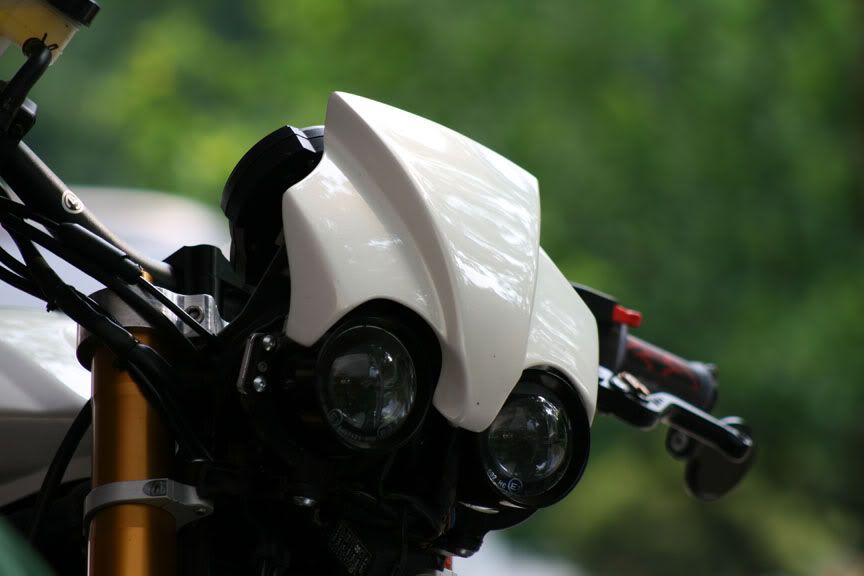
Next up was to cut a couple of holes in the bikini fairing mount so that the loom that attaches to the speedo could, er, attach to the speedo! This was a quick job with the Dremmel. As I mentioned previously this routing means the speedo sits as close as possible to the bikini fairing mount which looks much better than my original idea of raising the mount at least 20mm and having the loom bend sharply behind. I wasn't happy about having this bend in terms of possibly shortening the life of the loom at that bend and also the loom would have been much more visible and therefore untidy. Not the look I'm after.

Last job of the day was to make a small aluminium bracket to hold the air pressure sensor that sits in the nose of the Daytona above the lights. I was lucky that I could mount it in the same place on the new bikini fairing mount. This was made out of an L shaped piece of thin aluminium also kicking around the garage. I think I found it in a van I hired some years ago. Never throw anything away me! Drives Mrs Ruby Racing nuts! I'll probably paint this when I paint the speedo mount, but once the bikini fairing is in place it will be completely hidden.

Not sure what I can do next. Probably fit the longer throttle cable and do some cleaning. We'll see what the arm allows.
 

Attachments

#104 ·
Cheers k_petty, thanks for the feedback. Good to be back as I've been going nuts just watching TV, surfing the Net and reading. It may only be one handed spannering, but at least it's spannering.

Next up I hope to change the throttle cable and change the cam cover over. Might have found that I can order the long brake line for a Street Triple R, so that will solve my problems, just need to measure again. Measure twice, cut once as the old adage goes.
 
#105 · (Edited)
Day 19

Day 19

When I finished working today I stepped back to see what I had done. Not a great deal really! I put the Street Triple throttle cable on and the black cam cover. Yup that's it! It was a bit involved though. To get at the cam cover I needed to undo the throttle cable, but I could only do that by removing the injector assembly. This wasn't a problem, because as I said I had to change the throttle cable anyway. Bit of a bad design to have to remove the injectors though. On my GSX-R1000 K6 race bike you only have to lift the tank and the cables attach at one end of the injectors and are above the line of the frame. Dead easy and quick.

Getting the injectors off was a bit of a pain in the rear also. The injectors slip into rubber tubes which attach to the head. The fit is snug and then they are held in place with Jubilee Clips to keep them there. Now these are undone and done up by attaching a 3mm Allen Key to the screw that tightens them up. The one on the right is OK but the one in the middle is very hard to see. Luckily I have a bendy screwdriver so I got to it. The one on the left couldn't be got at with the bendy screwdriver because of the angle of the screw. So I had to undo that one with an Allen Key. As it was such a tight fit I could only turn the key about an eighth of a turn and then had to take it out and put it back in for the next turn. All this with only being able to get my fingertips on the Allen Key. Man that took some time and some swearing.

Then I tried to prise off the injectors, but they wouldn't budge. I thought it was because I could only use my good arm, so struggled for a while before undoing the Jubilee Clips some more. Ahhh. That did the trick. Off they came. Then I removed the air bleed hoses on the top of the cam cover. After that I attacked the cam cover. Only six bolts holding this on, most of which were rusty (after approximately 5,000 miles from new. That's a bit crap). I cleaned and painted those with some exhaust paint. Then I removed the air bleed valves to put them in the new cam cover. They were a tight fit in the original cam cover, but not so tight in the new cam cover. Hmmmm. Hope that won't be a problem. They're not going anywhere though, as they are held securely in place. I had bought a new cam cover gasket to be on the safe side, although the original would probably have been fine.

I changed the cam covers because I really dislike the golden brown colour of the original. I got hold of a new cam cover off eBay and it cost me the grand total of £3! I checked with my dealer. A new one is about £130. I think I was the only bidder and it was a garage that was selling it off. Guess not many people need new cam covers. The side casings are also going to change. I'm hoping I can just use paint stripper for those and then just leave an unpolished aluminium finish.

So apart from a bit more measuring up of the front bikini fairing mount, that's all I did. Can't believe it took about 6 hours! Still it was an enjoyable 6 hours and nice to be able to do some spannering again.
 

Attachments

#106 · (Edited)
Day 20

Day 20

Got a fair bit done recently. I've sanded down the speedo adapter plate to give it a smoother finish. I used some Nitromors paint stripper on the old cam cover to see if it would take the paint off. It does, but only if I use something abrasive to help the removal process. This has the effect of polishing the aluminium which I don't want. I tried using just a rag, but this isn't rough enough. What little it did take off gave me the result I was hoping for: a nice matt aluminium finish. I think I will have to investigate getting the cases bead blasted, as I'm told this will do what I want.

Most of my time has been spent fitting the bikini fairing mount. My first position was OK, but I wanted it closer and higher. To raise it I had to get my welding teacher to cut 20mm off the top and add 20mm to the bottom of the plates which sit in side the air intake in the headstock. This was as high as I could go as the bottom of the ignition barrel is as close as possible. This also meant I had clearance issues with my brake lever if I had it set as low as I like it. So I raised it a bit and then moved the mount backwards. It actually goes downwards slightly so this helped with the clearance issues with the brake lever.

I had to remove one of the screws that hold the bikini mount together, otherwise the ignition barrel would hit and I would not be able to turn the bars. You can see in the pictures where it has been removed. Good old Dremmel!

To cut a long story short I tried three positions, moving backwards 25mm from where I started. Much happier with this positioning. You can see the amount of holes I had to drill in the plates, which also had to have a thread tapped in them. That's the shot with the plate in the vice. The speedo is very close to the clutch and throttle cable, so I'm hoping this won't present a problem. I'll find out once I get her running again. I think that could be soon as I just need to get the new longer brake hose on (I've ordered a Triumph OE hose for a Street Triple R) and sort out the wiring for the lights and indicators (just ordered another block connector).

I also went to fit the loom guide that sits on the left of the headstock near the Factory plate. This is an OE item from a Street Triple so I assumed it was a direct fit. Wrong! The bottom hole doesn't line up. Had to ponder that one. Eventually I bent the loop outwards then drilled a hole for the screw that also holds the bikini fairing secure. Once I had the screw in place I could bend the loop back up. Sorted. Or so I thought. I couldn't now fit the loom in place as the screw was in the way. After a bit more thought I realised I would have to mount the cable guide first, then bend the bottom loop outwards, drop the loom in then bend the loop back up. Not an ideal solution, but I shouldn't be taking things apart all the time once I'm finished. At least I hope not, I just wanna ride.

My final problem I need to solve is the hole left between the top of the speedo and the top of the bikini fairing. It's the area I have outlined in red in one of the pics. I can't move the speedo up any higher for a couple of reasons, so that's out of the question. So as Jean Luc Picard was fond of saying on the bridge of Enterprise when they all had about 30 seconds before some huge event would wipe them from the face of the Universe: "Suggestions?"
 

Attachments

#108 ·
Maybe a bit of carbon fiber? A plate that shape, which could be a place to mount a switch or something. Or possibly an emblem, your coat-of-arms perhaps?
Good suggestion thanks.

I should have said I plan to make another speedo bracket which will be raised so that it follows the outline of the fairing at the top. Then I can mount some sort of instrument, something round or with a rounded top so that it looks like it's meant to be there. Initially I thought I could mount the GPS there, but it's too small a space. An ambient temperature gauge could be quite uesful. I've seen a battery LED volt meter that might suit. But you folks may have some better ideas. I'm all ears!
 
#110 · (Edited)
If I understand you correctly that's what I plan to do by extending the speedo mounting bracket. This will give me a sturdy base to attach something and thus fill the void.

So can anyone suggest some sort of instrument to fill that void? Must be someone out there with more imagination than me! It's the area in red on the photo that needs filling.

I did think about this battery condition LED gauge, but not sure I want bright LED's constantly on.
 
#111 ·
Seeing as I haven't looked into it, you could always sus out running a fuel guage or ACTUAL temp guage (not just bar indicators)?! I found it silly that our bikes, daytona & STriples have every other little gadget but no FUEL Amount/Bars or actual Temperature.

This is something I plan on looking into in the future! Whether or not it can be done/has been done is another story but that is just something extra I feel the bikes could have definitely had!

Otherwise buy a single DIN headunit with a built in screen & wire that bad boy direct to your battery with some plug in/out speakers for the helmet when you ride the long trips!! :p chuckles

Btw, did I read that you might be mounting the lights/guages, etc to the bars so that it all moves together?! I know people have done something similar BUT the reason I ask is, that all the people who have chosen to run clippons on the STriples have clearance issues with stuff touching lock to lock! I can only imagine if everything moved together, we wouldn't have that problem & thus, be able to use the visor/fly screen still - just so you know, with clipons & standard mounted headlights/guages, they can be made to clear, but not enough so that the visor can stay on! :( An item I feel I'd like to keep if I ever put clipons on my bike!

& breathe!! End rant! Good luck with it all mate.
Daniel.